2013年12月26日星期四

Fiber Optic Polishing Paper

Fiber Optic Polishing tools play an important role in fiber optic installation. They are specially used in fiber industry for polishing the end face of fiber optic product. In FiberStore  fiber optic polishing catalogs, you will find our fiber optic polishing machines and other fiber opolishing machine kits including fiber polishing fixture for all types of fiber connectors, fiber optic polishing puck and fiber optic plishing paper. Fiber optic polishing paper is using latest developments of international Ultra-precision coating technology, uniformly dispersed the abrasive powder micron and nanometer (diamond, white fused alumina, silicon carbide, silicon oxide, cerium oxide, iron oxide, etc.) and new polymer material on the high-strength film surface. fiber optic polishing paper The main purpose of fiber optic plishing paper: Optical fiber connectors, couplers, attenuators polishing. Ceramic ferrule, plastic inserts, glass tube hairs polishing. Optical devices, optical crystal polishing. Features: Evenly-sprayed particles on coated surfaces. Submicron powder particles make high polishing accuracy. Positioned lapping & polishing to save abrasive materials. Fine curved surface polishing effects because of flexible substrate. Suitable for polishing with dry, water or oil. Main Specifications of Diamond Polishing Films
UND0.5 UND1 UND2 UND3 UND6 UND9 UND15 UND30 UND45
Size( μ m) 0.5 1 2 3 6 9 15 30 45
Mesh 10000 8000 6000 4000 3000 2000 1200 600 400
Round Specification(mm) Φ 70 / Φ 110 / Φ 127 / Φ 203
Square Specification(mm) 114 × 114 / 152 × 152 / 228 × 228
Banding(mm) 1.6 / 2.0 / 2.5 / 3.2 / 3.8 / 101.6
Fiber optic using Life: While you optimize optical performance of fiber optic connector,  try to extend the service life of the grinding sandpaper/ploshing paper. Each ploshing 14 fiber connectors change to use of different parts of the ploshing paper. Use five parts of one ploshing paper  can ensure that each ploshing paper can grind 70 fiber connectors. Additional, The amount of binder on the tips and the pressure of the polishing can affect the paper life. Our high quality fiber optic polishing products helps to ensure that there will be no defects in your fiber end faces that could degrade the transfer of light. Buy our fiber optic polishers on our worldwide online store with confidence.

2013年11月6日星期三

How about testing mpo/mtp cable


To understand the challenges of MPO cable validation, it’s necessary to understand MPO cables and how they’re tested in the field. An MPO connection is about the size of a fingernail and contains 12 optical fibers, each less than the diameter of a human hair – and each one needs to be tested separately. That traditionally means the use of a fan-out cord to isolate each fiber, followed by tedious manual testing, tracing, and error-prone calculations.
Testing and determining fiber polarity is another challenge. The simple purpose of any polarity scheme is to provide a continuous connection from the link’s transmitter to the link’s receiver. For array connectors, TIA-568-C.0 defines three methods to accomplish this: Methods A, B, and C. Deployment mistakes are common because these methods require a combination of patch cords with different polarity types
So what would a proper MPO test look like? The answer is simple: Test all 12 fibers – the whole cable – simultaneously and comprehensively (including loss, polarity, etc.). That sort of test capability changes the fiber landscape, enabling installers and technicians to efficiently validate and troubleshoot fiber – flying through the process by tackling an entire 12-fiber cable trunk with the push of a button.
The tools to perform this type of test are just emerging on the market, and promise to reduce the time and labor costs up to 95% over individual fiber tests (according to internal research based on the average list of standard competitive products). Characteristics to look for in such a tool include:
An onboard MPO connector to eliminate the complexity and manual calculations associated with a fan-out cord.
A single “Scan All” test function that delivers visual verification via an intuitive user interface for all 12 MPO fibers in a connector.
Built-in polarity verification for end-to-end connectivity of MPO trunk cables.
“Select Individual Fiber” function that enables the user to troubleshoot a single fiber with more precision.
Demand for fast and reliable delivery of critical applications is driving data center technology to evolve at an ever-increasing pace. And that insatiable need for bandwidth ensures that the integrity of the data center has become inextricably linked to the strength of the fiber cabling infrastructure. The growing use of MPO fiber trunks – and the migration from 10-Gbps to 40/100-Gbps connections – means that it’s time to stop the cumbersome verification of individual fibers. After all, it’s a single MPO connection. You should be able to test it as one.
You can buy fiber optic jumpers with mpo/mpo connectors  from FiberStore now!

2013年11月5日星期二

More bandwidth means more testing


The use of MPO cables for trunking 10-Gbps connections in the data center has steadily risen over the past 10 years. That trunking requires use of a cassette at the end of the MPO cable designed to accommodate legacy equipment connections. Now that 40-Gbps and 100-Gbps connections are coming on the market, a migration path has emerged: Remove the 10-Gbps cassette from the MPO cable and replace it with a bulkhead accommodating a 40-Gbps connection. Then it might be possible to remove that bulkhead and do a direct MPO connection for 100 Gbps at a later date.
The problem is that while this migration strategy is an efficient way to leverage the existing cabling, in comparison to 10-Gbps connections, the 40-Gbps and 100-Gbps standards call for different optical technology (parallel optics) and tighter loss parameters.
In short, each time you migrate you need to verify the links to ensure the performance delivery the organization requires.
To understand the challenges of MPO cable validation, it’s necessary to understand MPO cables and how they’re tested in the field. An MPO connection is about the size of a fingernail and contains 12 optical fibers, each less than the diameter of a human hair – and each one needs to be tested separately. That traditionally means the use of a fan-out cord to isolate each fiber, followed by tedious manual testing, tracing, and error-prone calculations.
The actual fiber test is quick enough: typically under 10 seconds per fiber once you’re in process. But you better be cruising: While one of our enterprise customers has data centers with as little as 24 MPO fiber trunks (x12 fibers each), that same customer also has a 30,000-MPO data center installation. That’s 30,000 connections with 12 fibers each, or roughly 3,120 hours in labor (and $343,200 in cost) if you had to test them all individually.
And at some point, you better have tested them. There were two primary drivers behind development of MPO fiber trunks. The first was the ever-increasing need for cabling density in the data center. Cabling blocks airflow, so the denser the cable, the better the thermal management. And, as data center bandwidth steadily climbs to 10, 40, and 100Gbps, a dense multi-fiber cable becomes the only option.
But the second, perhaps more important factor, is the difficult and highly technical nature of field termination for fiber. We’re talking curing ovens, adhesives, microscopic fibers, etc. Given that expensive and time-consuming “craft” process, modular factory-terminated MPO cables promise simplicity, lower cost, and true plug-and-play fiber connectivity.
The challenge is that pre-terminated fiber is only guaranteed “good” as it exists in the manufacturer’s factory. It must then be transported, stored, and later bent and pulled during installation in the data center. All kinds of performance uncertainties are introduced before fiber cables are deployed. Proper testing of pre-terminated cables after installation is the only way to guarantee performance in a live application. In short, investing in factory-terminated fiber trunks to save time and decrease labor costs doesn’t really offer an advantage if the testing becomes an expensive bottleneck.
Testing and determining fiber polarity is another challenge. The simple purpose of any polarity scheme is to provide a continuous connection from the link’s transmitter to the link’s receiver. For array connectors, TIA-568-C.0 defines three methods to accomplish this: Methods A, B, and C. Deployment mistakes are common because these methods require a combination of patch cords with different polarity types.
You can buy fiber optic jumpers with any connectors from FiberStore.

Fiber optical system operating wavelengths


A wide range of the optical system operating wavelengths can provide a very high capacity for the optical transmission system. The optical fiber type, source characteristics, system attenuation rang and dispersion of the optical path decide the operating wavelength range.
Singlemode fiber system spectral bands in ITU-T Recommendations:
1) “Original” O-band, 1260nm to 1360nm
Cable cut-off wavelength decide the lower limited wavelength is 1260nm. The upper linit 1 360 nm was chosen as to the rising edge of the “water” attenuation band peaked at 1 383 nm
2) “Extended” E-band, 1 360 nm to 1 460 nm.
Recommendation ITU-T G.652 also includes fibres with a low water attenuation peak, which
allows the utilization of the band above 1 360. The effects of a small water peak are negligible
at wavelengths beyond about 1 460 nm;
3) “Conventional” C-band, 1 530 nm to 1 565 nm.
Initially, erbium-doped fibre amplifiers (EDFAs) had useful gain bands beginning at about
1 530 nm and ending at about 1 565 nm. This gain band had become known as the “C-band”;
4) “Short wavelength” S-band, 1 460 nm to 1 530 nm.
The lower limit of this band is taken to be the upper limit of the E-band. The upper limit is
taken to be the lower limit of the C-band. EDFAs have become available with relatively flatter
and wider gains and application of EDFAs to this band is possible at least in a part of the band.
Some wavelengths of this band may also be utilized for pumping of optical fibre amplifiers,
both of the active-ion type and the Raman type;
5) “Long wavelength” L-band, 1 565 nm to 1 625 nm.
For the longest wavelengths above the C-band, fibre cable performance over a range of
temperatures is adequate up to 1 625 nm for current fibre types;
You can buy fiber optic jumpers and fiber pigtails from FiberStore now!

2013年11月4日星期一

FiberStore Info

http://www.youtube.com/v/ep1f1B3HlI8?autohide=1&version=3&attribution_tag=s7vqwtEbDSbQu8HYtlp7-g&feature=share&autoplay=1&autohide=1&showinfo=1

2013年10月31日星期四

The factors which will affect the fiber splicing result


I get the answer from a professional fiber splicing engineer- William Graham
He tell that:
1 Keep the fiber splicer and fiber cleaver in the case when not in use.
2 Be sure you are set on the proper splicing program for the fiber you are splicing.
3 Don't expect good splices under adverse conditions of dirt, dampness and wind. Create good splicing conditions.
4 Keep the dome and heater covers closed unless you are splicing or heating
5 Close the cleaves as soon as you take out the cleaved fiber
6 Clean your splicer before you start splicing.
7 Use an air bulb and fine brush for cleaning.
8 Do not used spray cans or the propellants might do damage.
9 If splicing gel filled cable ensure it is really clean so you don't gum up the splicer.
10 Clean any gummed up grooves with a piece of sharp wood. Never use metal.
11 Charge the battery when you finish. The splicer we use will do over 200 splices and heats on a charge.
12 Have a stable and secure place for your splicer when splicing. If it drops on the floor it is probably garbage.
13 Keep your shrink splice sleeves in a sealed container (ziplock bag)
14 If you drop the shrink splice sleeve on the floor, leave it there.
15 Never clean the fiber with alcohol after you have cleaved it or you might cause reflections.
16 Have the splicer serviced (calibrated) when necessary
17 Clean the cleaver before you start with a fine brush and alcohol, especially if using gel filled cable.
18 Close the cleaver between cleaves to keep out air-borne dirt.
19 And, finally, if you drop the cleaver on the floor its value will be drastically diminished.
Manage your fiber ends and empty the scrap container at the end of the day.
Do the splice job as above points, you will get a good splice. Additionally, I also have a write a tutorial about fiber splicing process. You can read all from here. http://www.fiberstore.com/Optical-Fusion-Splicing-Tutorial-aid-350.html and if you need fiber optic jumpers also can sent requriments to sales@fiberstore.com

2013年10月18日星期五

A clear understanding of the difference between fiber pigtail and patch cord


Previously, I only know different in appearance of the fiber pigtail and patch cord.
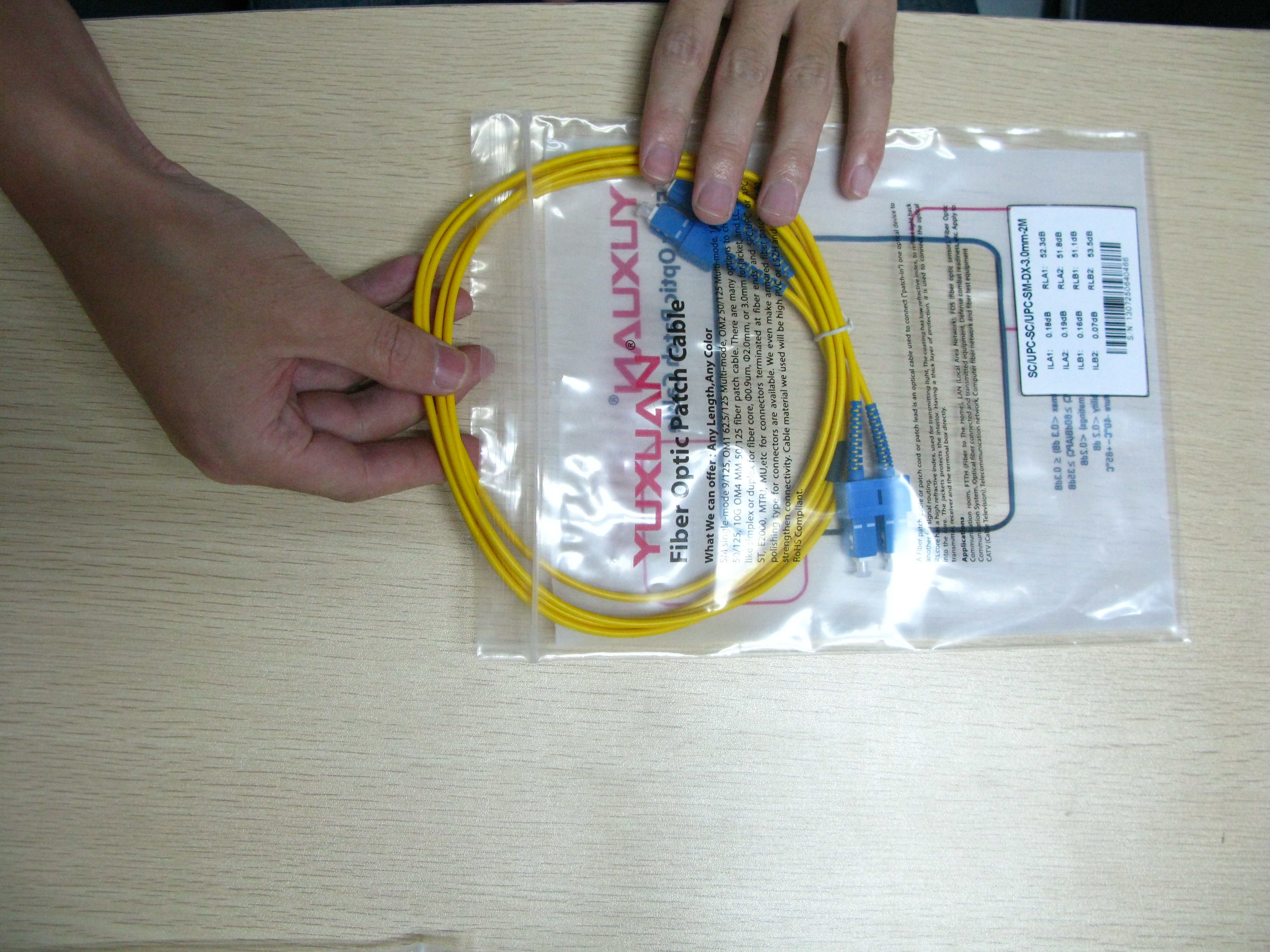
The fiber optic patch cord = fiber optic connector + fiber optic cable + fiber optic connector
IMG_5915
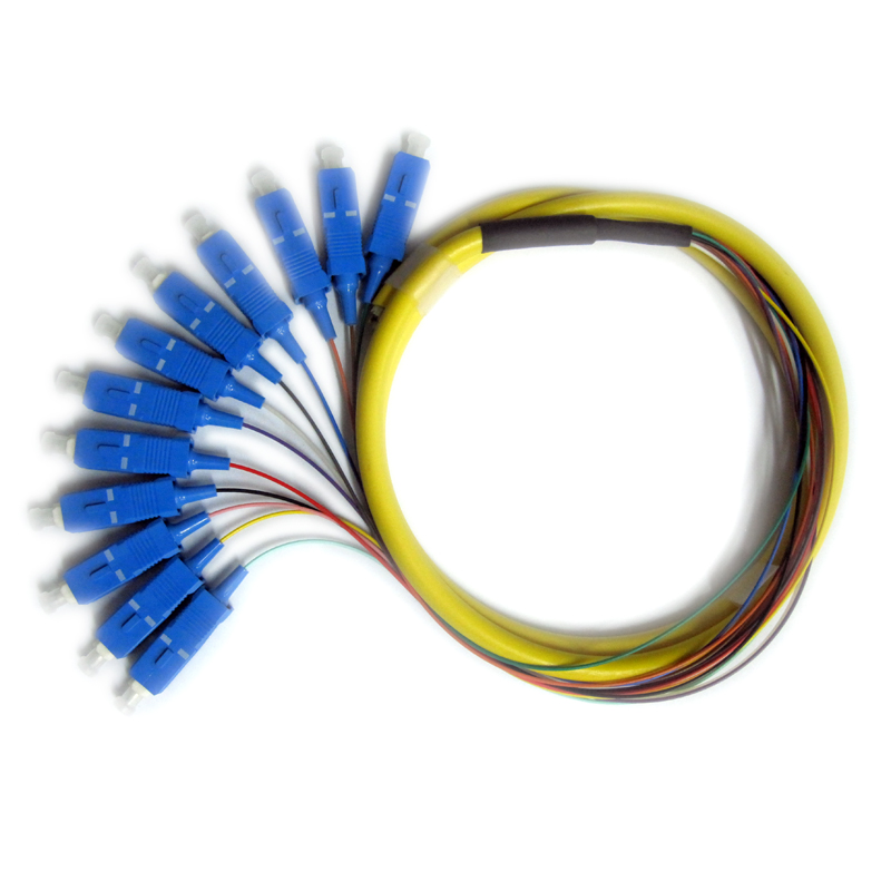
but the fiber optic pigtail = fiber optic connector + fiber optic cable. I think like this is easy to separate between them.
12fibers SCUPC SM pigtail
Recently, I have readed a discussion about the difference between fiber pigtail and patch core. There are so many professinal people to discuss it. They give me a clear understanding that:
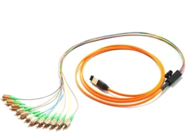
Patch cords are made from either single or multi-fiber cables (usually rated for indoor use) and connected at each end with fiber cable connectors (either single fiber or multiple-fiber connector). Sometimes patch cords are called jumpers, especially if they are simplex or dulex. The connectors are selected to mate with the interfacing equipment or cable connectors. The important idea is that the cable has a connector at each end. The fiber can be either tight or loose buffered and the cable can be made of various diameters (1.2 mm to 3.0 mm are common). The patch cord may have one type of connector (ST FC, SC, LC, etc) on one end and a different connector on the other as long as all the fibers are connectorized on each cable end - this is a transition jumper. Patch cords are commonly used to connect ports on fiber distribution frames (FDFs). The  new mpo connecter make it  possible to run a singel cable that automatically terminates 12 fibers in one easy plug in.  Compared to common patch cord with ST FC, SC, LC connetor, MPO cable is a truly innovative and amazing group of products that really takes fiber optics into the new millennium.
mtpmpo3
A pigtail is a cable (like a pach cord or jumper) with only one end terminated with an optical connector. Patch cords are often cut into shorter lengths to make two pigtails. Pigtails are found anywhere, but more commonly in optical assemblages or optical components
Pigtails are installed where they will be protected and spliced,lets say on the inside of the ODF and that's why they are normally not sheathed. They have a coating colour so that you slice them on the corresponding colour on the out coming fiber.
On the other hand patch codes are used between the ODF to the WDM MUX or equipment. If you cut a patch code for use as pigtail then in case of future faulting where you are dealing with multiple pairs it will be difficult. But still if you need to cut the patch code check on its characteristics.
In general, the only major physical differnce b/w patch cord & pigtail is that patch cord is a fixed length piece of cable with dual ended fiber connector type may vary & pigtail is one meter standard OFC core with white white colored jacket. As per standard pigtail can only be used for OFC termination purpose & patch cord is to be used to connect the active component with ODF so that means pigtail can not be used at the place of patch cord.